Electron Infrastructure
Laser System
Operating Modes

Layout
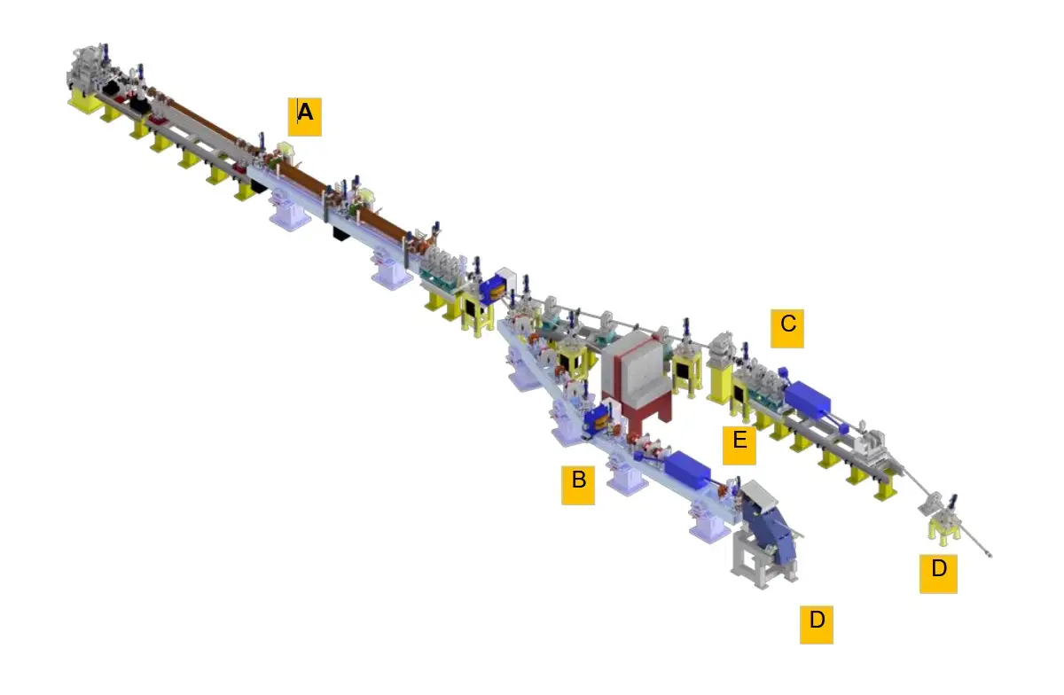
A. Acceleration Section (1 S-band LINAC and 2 C-band LINACs)
B. High-Energy Section "STAR-HE-Linac"
C. Low-Energy Section "STAR-LE-Linac"
D. Beam Dump
E. Impact Chambers
Enhanced layout of the STAR Inverse Compton Source (ICS) for hard X-ray production, designed by the National Institute for Nuclear Physics (INFN) (A. Bacci et al., STAR HE-Linac Complete Detailed Design Report, arXiv:2109.10351v1).
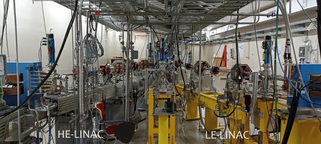
This configuration includes two beamlines, referred to as the "low-energy" (LE-linac) and "high-energy" (HE-linac) lines, powered by a linac capable of accelerating electron bunches up to a maximum of 150 MeV. The previous layout (STAR-1) consisted of a single beamline with a maximum energy of 65 MeV.
Technical specifications

The new HE-linac is designed to power an Inverse Compton Scattering (ICS) source with X-ray emission up to a maximum photon energy of 350 keV, requiring an electron beam energy of approximately 140 MeV. To achieve this goal, the acceleration capacity of the STAR-1 linac has been enhanced with the addition of two C-band acceleration sections. The chosen value of 150 MeV accounts for safety margins, particularly concerning the injection phases into the RF cavities, to effectively compensate for beam energy dispersion.
An 8 cm-long compact solenoid has been incorporated just before the initial S-band cavity. This solenoid, generating a peak Bz field of approximately 0.2 T, enables more precise control of beam divergence and compensation for divergence over a wide range of energy operations.
With the incorporation of two additional C-band linear acceleration sections, beam energy dispersion can be suppressed—a technique that was not possible with the previous layout. This approach is applicable to both the LE-linac (with an operating energy range between 23 and 65 MeV) and the HE-linac (with an operating energy range between 40 and 150 MeV).


